
Assembly steps and requirement of CNC metal spinning machine tool
The assembly of CNC metal spinning machine
The design, machining accuracy and assembly accuracy of the CNC spinning machine are important factors determining the performance of the spinning machine. This article focuses on explaining the assembly steps and requirements of the CNC spinning machine.
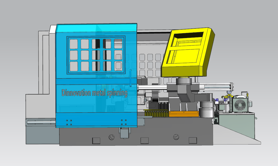
What is CNC metal spinning machine >
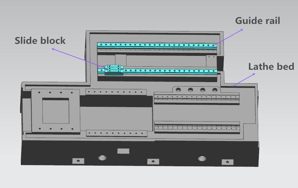
1. Z-axis guide rail assemble on the lathe bed
① Clean surface
Before installing the lead screw, wipe the contact surface between the guide rail and the lathe bed clean with a cloth to prevent dust, iron filings affecting the assembly accuracy.
② Tightening screw requirement
The screws for tightening the guide rail and the pressing block need to be installed and tightened from left to right in sequence, and then the tightening force should be applied to the screws in three steps.
③ Inspect the accuracy
Taking one of the guide rail as the reference, put the dial indicator on the slide block, to inspect the parallel of another guide rail. Generally, the tolerance should be controlled within 0.02mm per meter.
④ Lubricating oil
Adding lubricating oil to the rollers inside the slider of guide rail, to prevent the rollers from wearing out too quickly due to lack of lubricating oil when the machine is in operation.
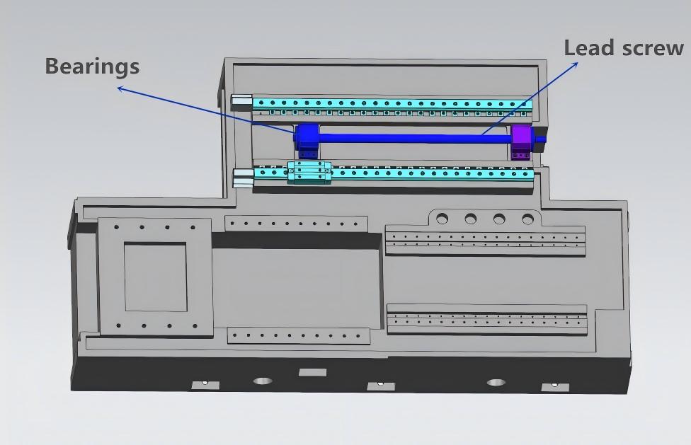
2. Assemble the Z-axis lead screw and bearings
① Bearings
Add lubricating oil to the bearings, then Assemble the bearings and lead screw together.
② Control parallelism tolerance
The parallelism between the lead screw and the linear guide needs to be controlled within 0.02mm.
③ Pins
Drilling positioning pins on the bearing housing.
3. Assemble the X-axis lead screw and bearings
The step of A -axis lead screw and bearing assembling is similar with Z-axis, it need to control the parallelism between lead screw and guide rail with 0.02mm.
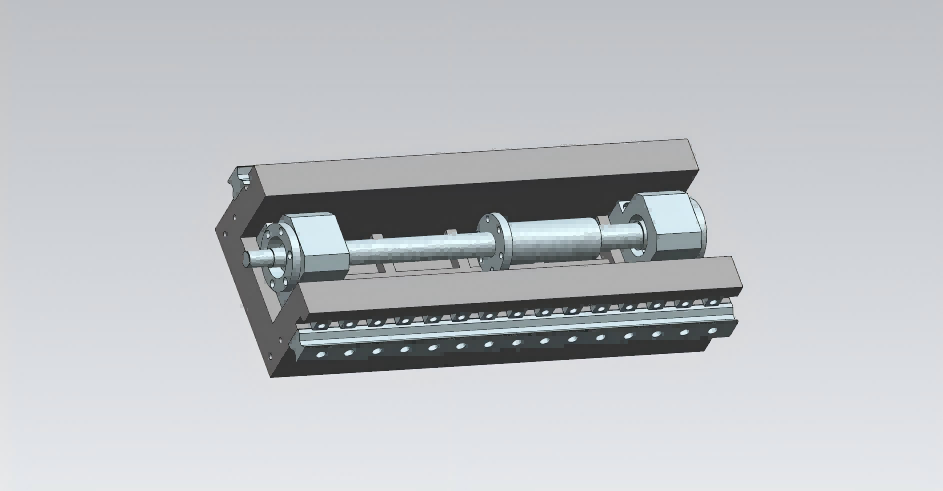
4. Assemble the cross slide
The function of the Cross slide is assembled the X-axis and Z-axis together, it need to scrape to make sure the The parallelism between A-axis and Z-axis within 0.02mm.
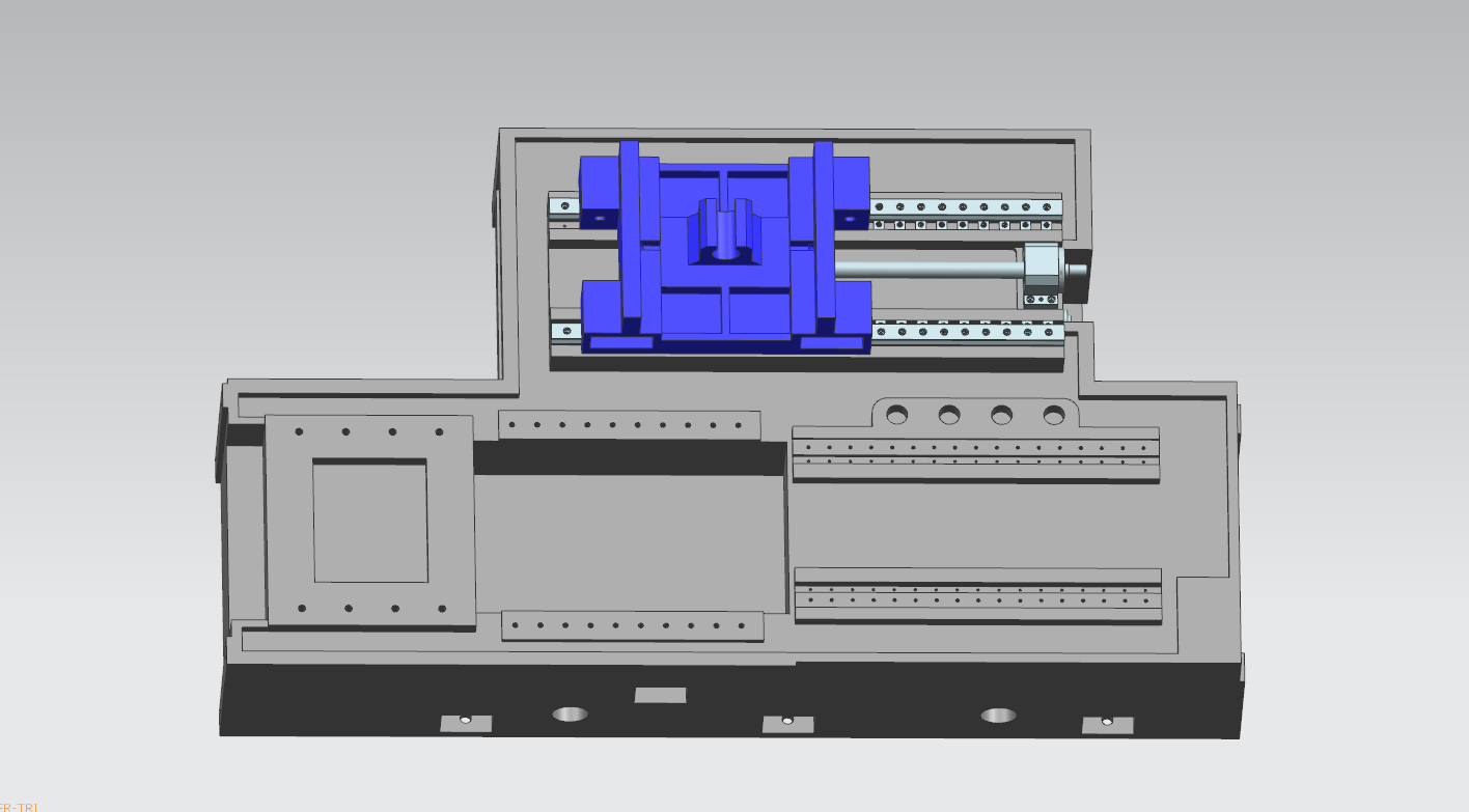
5. Put the X-axis in the cross slide
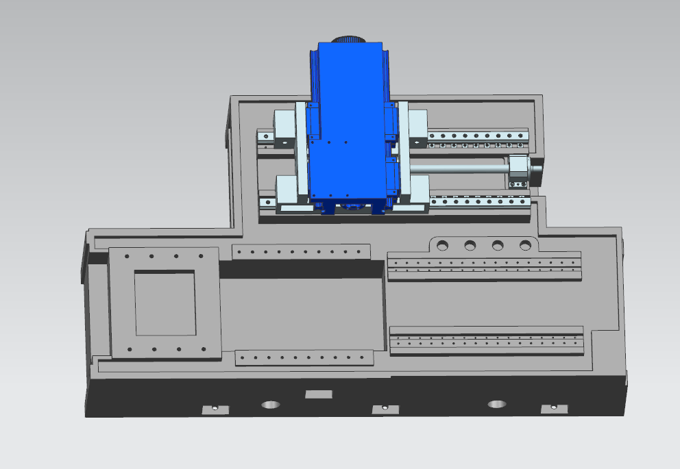
6. Assemble the Shim inside
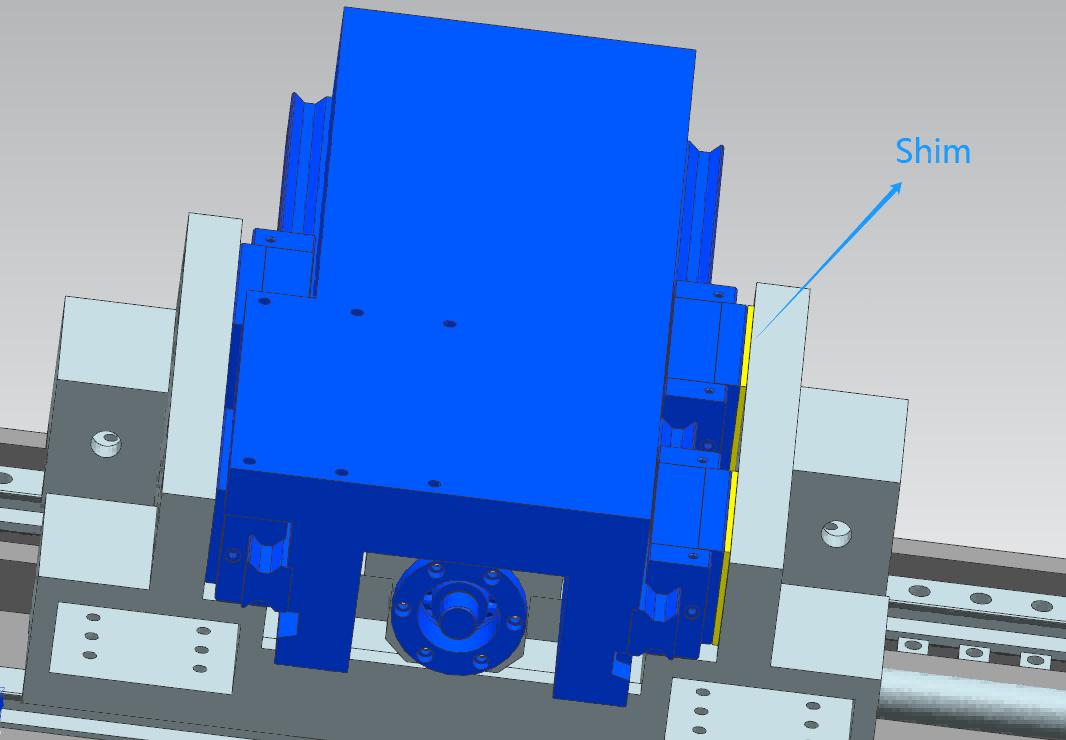
Shim is used to eliminate cumulative errors in machining. Generally, shim are designed to be thicker. After assembly, the actual gap is determined by grinding to achieve a tight fit.
There are two position is assembled shim in the cross slide, one is to control the X-axis, another is to control the Z-axis.
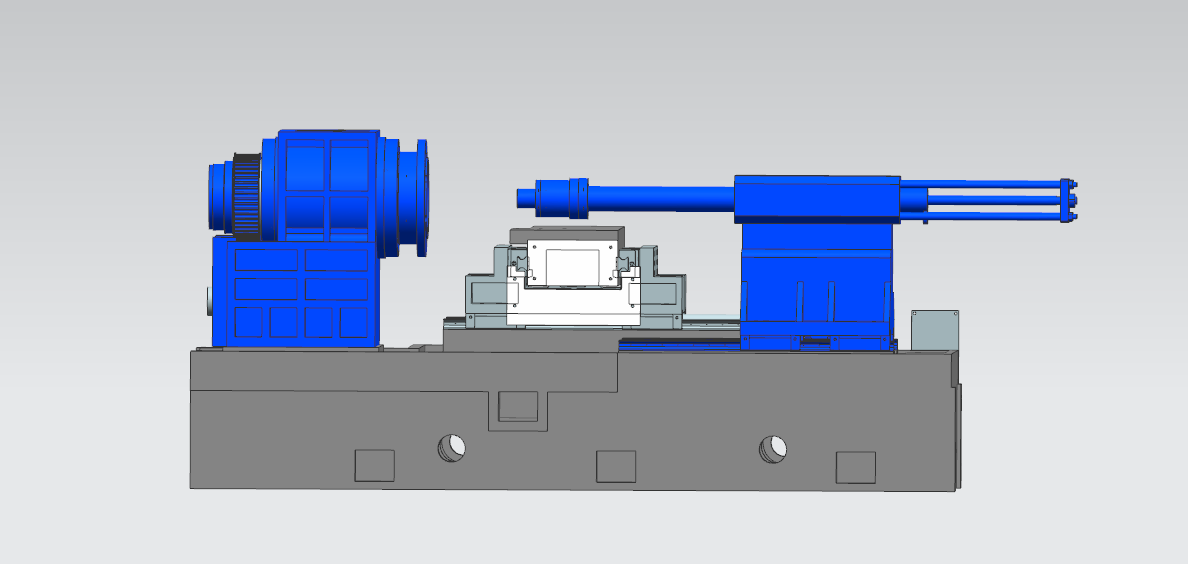
7. Assemble headstock and tailstock
① Headstock
It is used to assemble spindle, The smaller the clearance between the spindle hole and spindle is better, Good factories take advantage of the principle of thermal expansion and contraction to freeze the spindle. After the size of the main shaft is reduced, it is easier to install it in the spindle hole. When the main shaft expands to its normal size at room temperature, the assembly gap basically disappears.
● Dynamic balance
The spindle needs to undergo dynamic balance testing to reduce noise and centrifugal force during rotation and increase the working life of the bearings.
● The parallelism
The parallelism of the spindle and the Z-axis needs to be controlled within 0.02mm.
② Tailstock
it is used to assemble hydraulic cylinder, in order to make sure the centre of spindle is same with the centre of hydraulic cylinder, it can design a shim to increase the height of tailstock, it is convenient to grind shim to adjust the height.
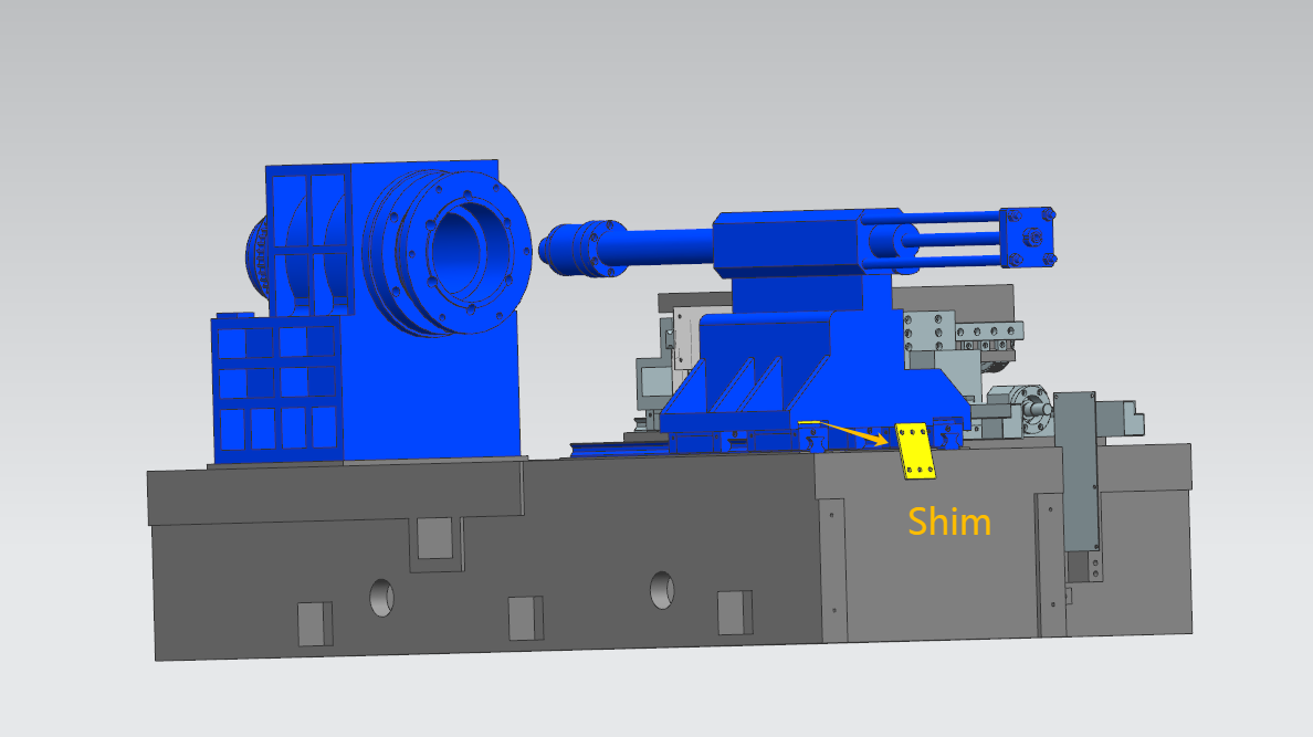
8. Asseble the tool mounting
Assembling the tool mounting on the X-axis table, to use a shim to adjust the height to control the spindle centre and tool mounting centre within 0.02mm, otherwise it is easy to shake when spinning roller and turning tool working, and the spinning roller and turning tool can't arrive the spindle centre.
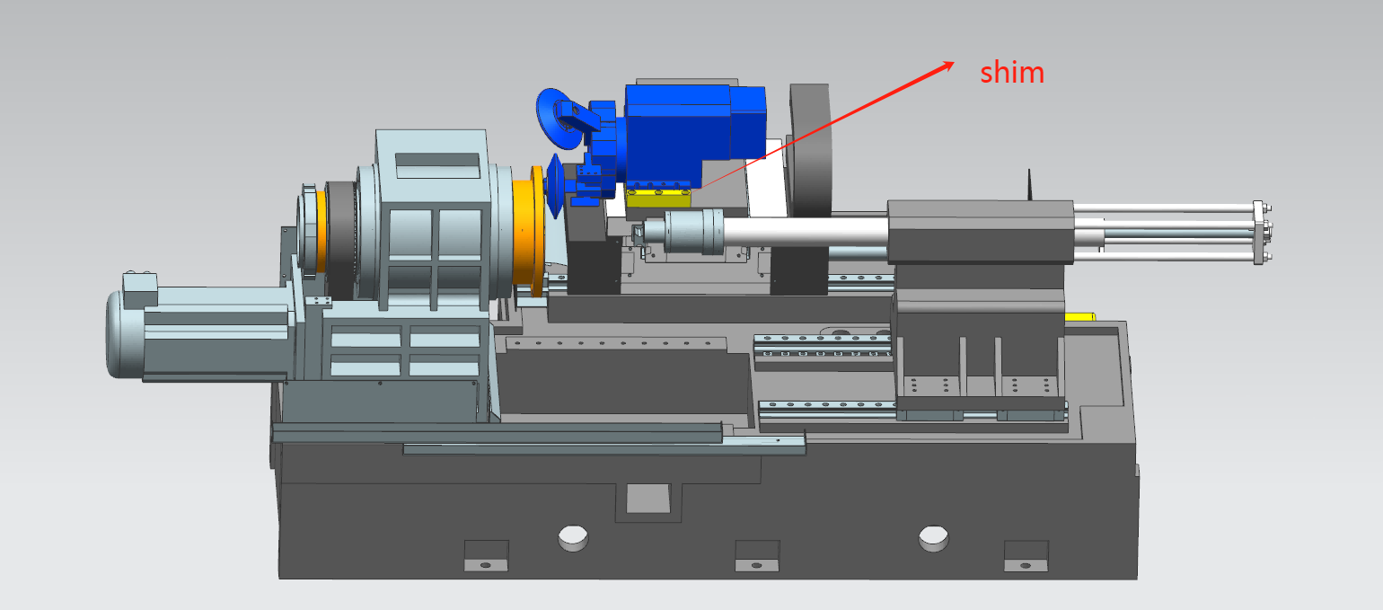
9. Assemble the motor
① Spindle motor
● Overload protection
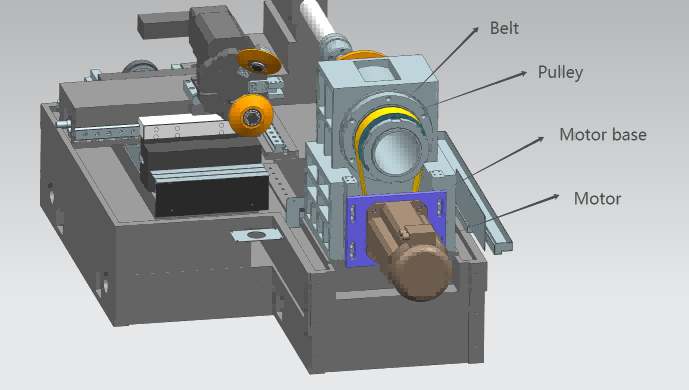
Spindle motor output the Torque and drive the spindle to rotate through the pulley mechanism, When the main shaft is subjected to relatively large forces, the belt will slip, which serves as overload protection.
● Preload mechanism
The pulley mechanism needs to be designed with a preload mechanism.
● Deceleration increases torque
Torque and spinning force can be increased by adjusting the reduction ratio of the pulley.
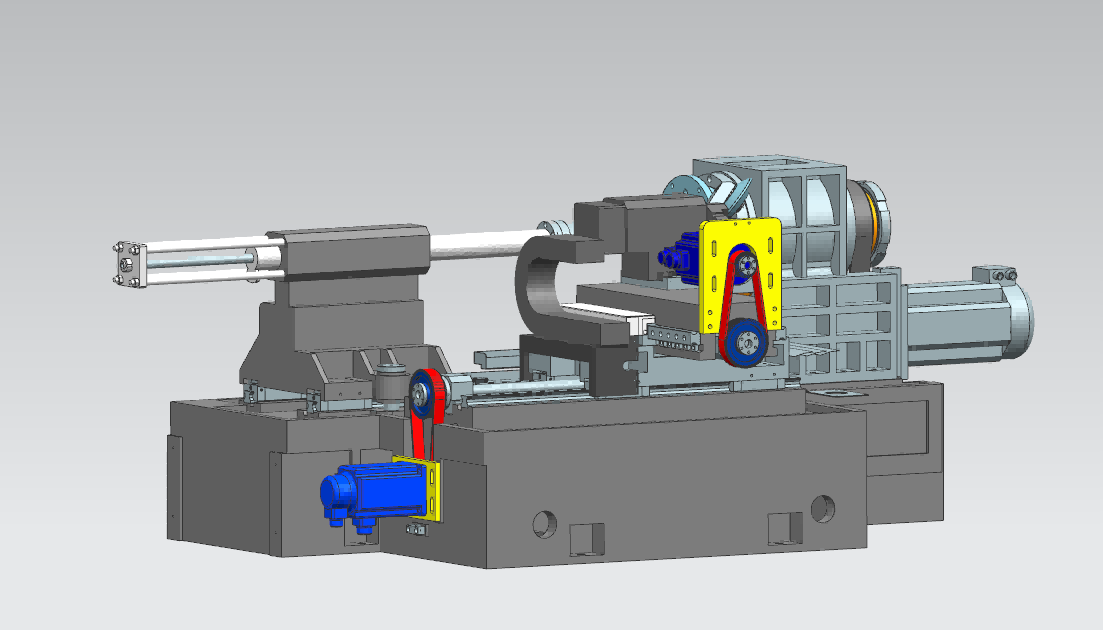
② X-axis and Z-axis motor
The motor power of X-axis and Z-axis is less than spindle, because spindle not only is loaded spinning force, but also loaded the hydraulic force of tailstock and take mold to spin. X- axis and Z-axis motor can be used Pulley mechanism, it also can be connected by Planetary reducer.
10. Hydraulic station
It is used to output hydraulic pressure, It is mainly composed of a motor, a pump, a hydraulic valve, oil pipes and a fuel tank. Oil pipe is connected with the hydraulic cylinder.
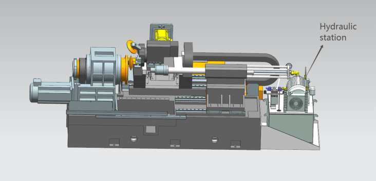
11. Lubricating pipe
Lubricating pipe need to connect the guide rail slider, lead screw, it require regular lubricating oil addition to reduce wear for machine maintenance.
12. CNC System and sheet metal shield
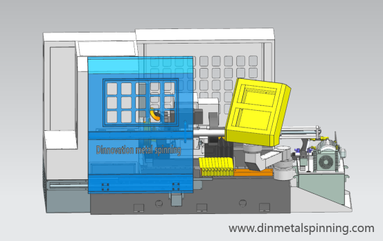
At last, we assemble the CNC system and sheet metal shield, A CNC metal spinning machine assembly is finished.
Recommended
- -Top twelve metal forming fabrication methods
2025-11-22 - -What is CNC metal spinning machine tool
2024-08-15 - -Aerospace components-Precision manufacturing of CNC spinning
2025-01-29 - -Metal spun products - what product spin forming can do
2025-01-24 - -How to design a CNC metal spinning mold | mandrel
2024-04-12 - -Metal spinning materials
2024-04-14 - -Metal spinning development and prospect
2024-10-31 - -How to choose a CNC metal spinning machine
2024-04-18 - -Metal spinning process and technology
2024-11-30 - -How to control the accuracy of CNC metal spinning
2024-07-27
